Key tools (measure, move…): Difference between revisions
No edit summary |
No edit summary |
||
| Line 141: | Line 141: | ||
</table> | </table> | ||
<span class="btnretour">[[#top| | <span class="btnretour">[[#top|Back top of page]]</span> <span class="btnhome">[[Creating a new project|Next step]]</span> | ||
Revision as of 16:28, 5 July 2023
|
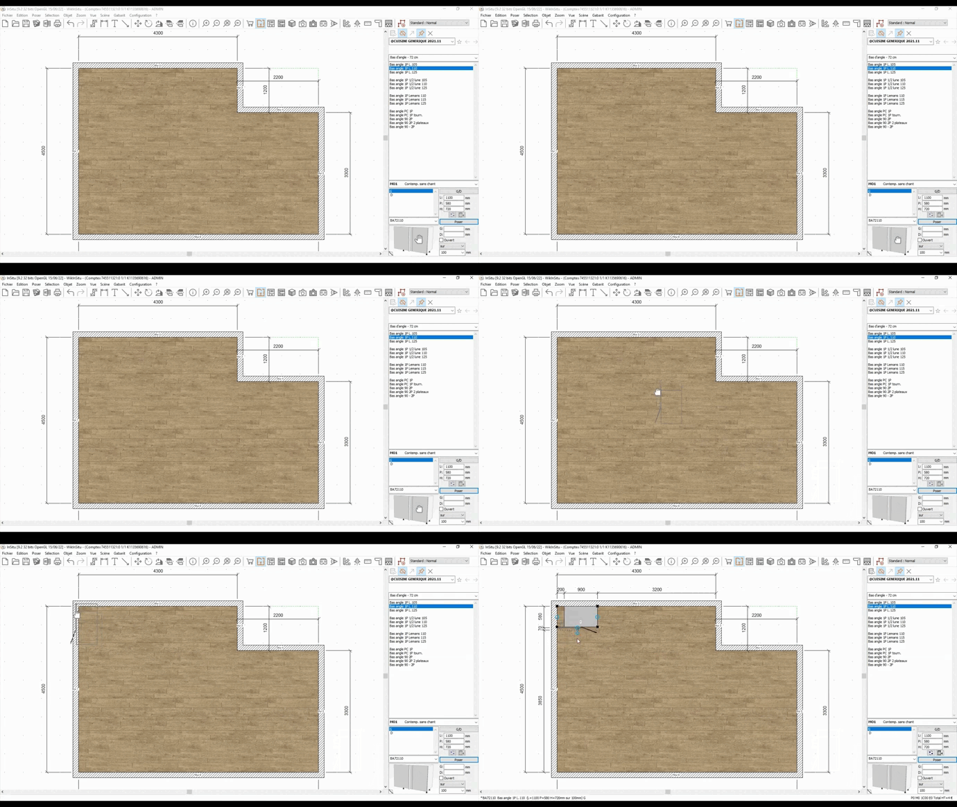
ANCHORAGE POINT To automatically place some elements (low furniture, decorative objects, ...) against a wall or to align various elements, InSitu makes use of "anchorage points". Anchorage points are crucial to how InSitu works and understanding how they work will help you better place and position your elements in your projects. Each graphical element is made up of several anchorage points. They are represented by black squares and they appear when you select an element. Let's take a piece of angle furniture and place it in the angle of a wall without considering which direction we drop it in.
Thanks to the anchorage points, the piece of angle furniture places itself automatically in the joining of the two walls and in the right direction. Via shapes, it is possible to add anchorage points to a project. This can help you, for example, to place the furniture of a central island. We will see how these anchorage points are useful for moving objects with the "move" tool or to make measurements.
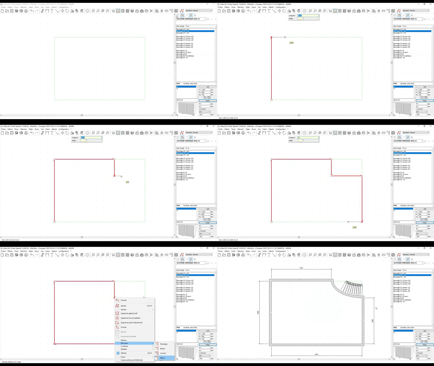
Shapes are one of the key features of the InSitu software. They are used to create uniquely shaped worktops, to create complex room layouts, to lay wall tiles, to place ceilings on underslopes, to create anchorage points and many more functions.
An entire chapter is dedicated to the mastering of shapes. Here is the link.
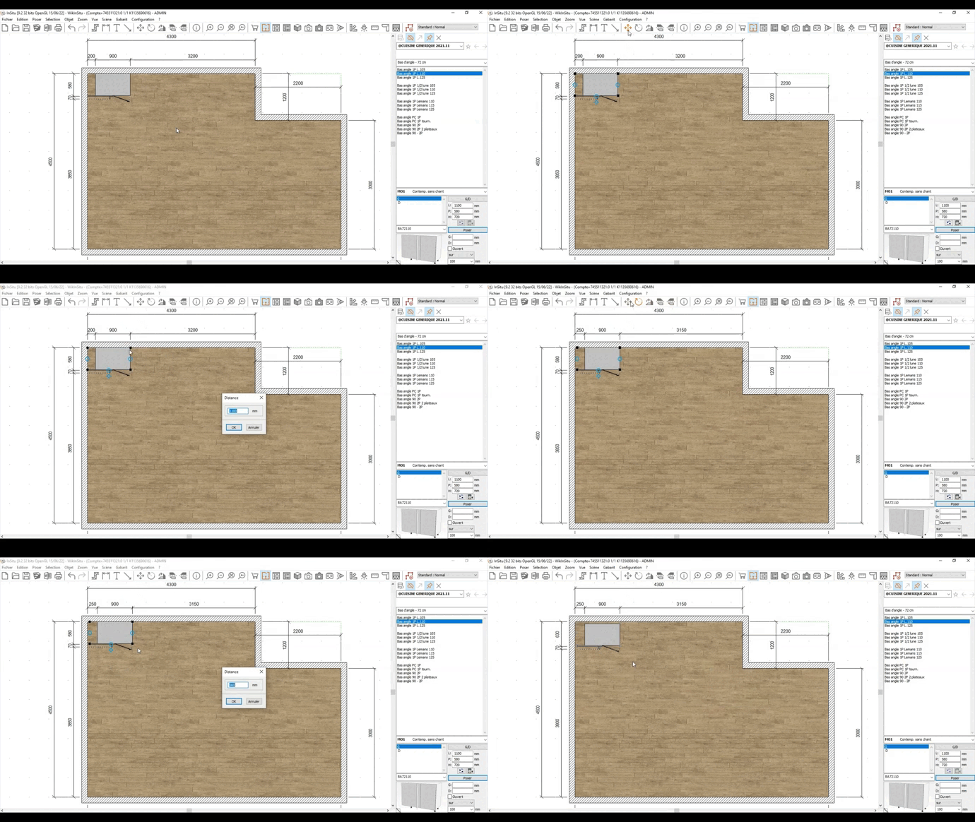
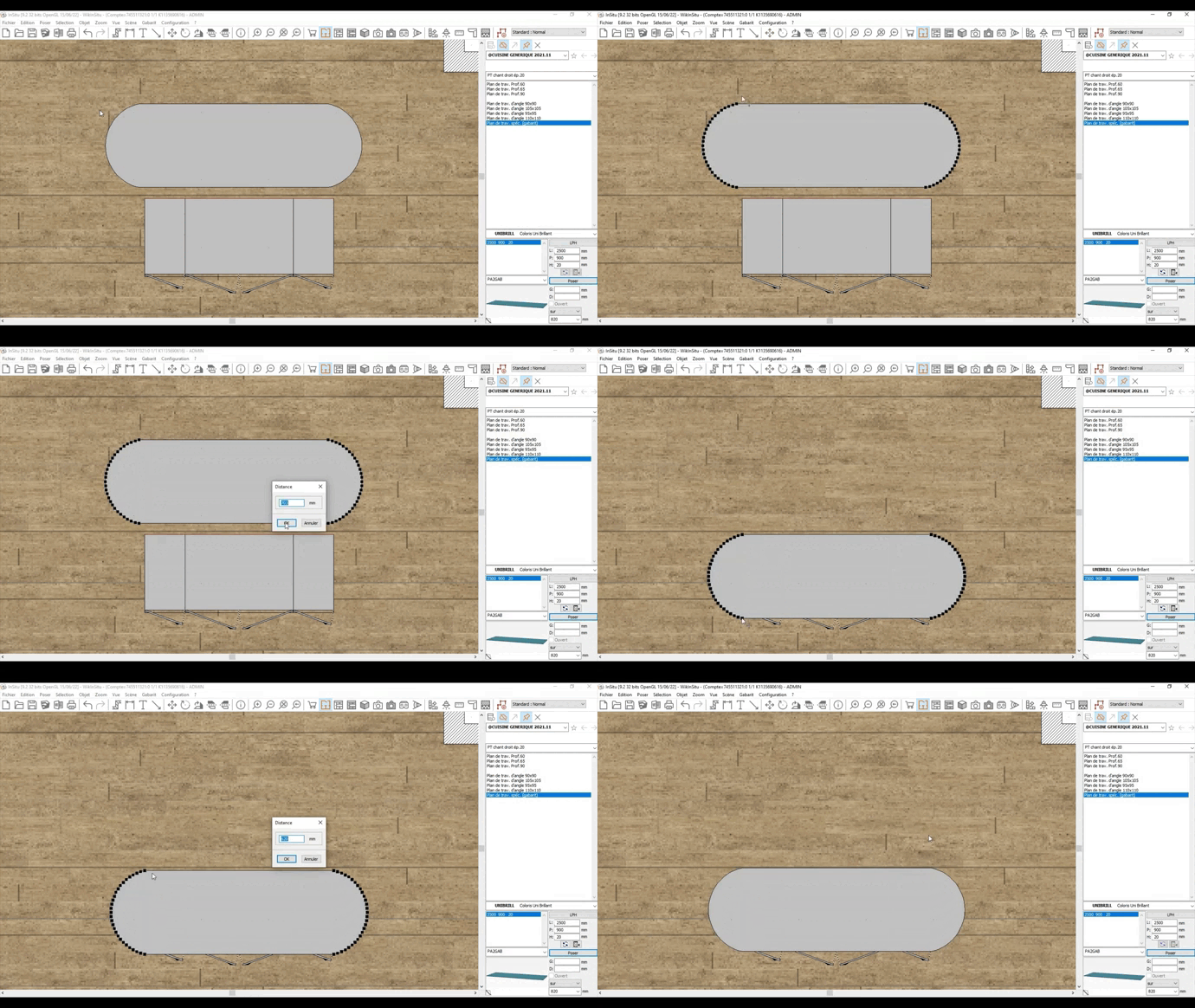
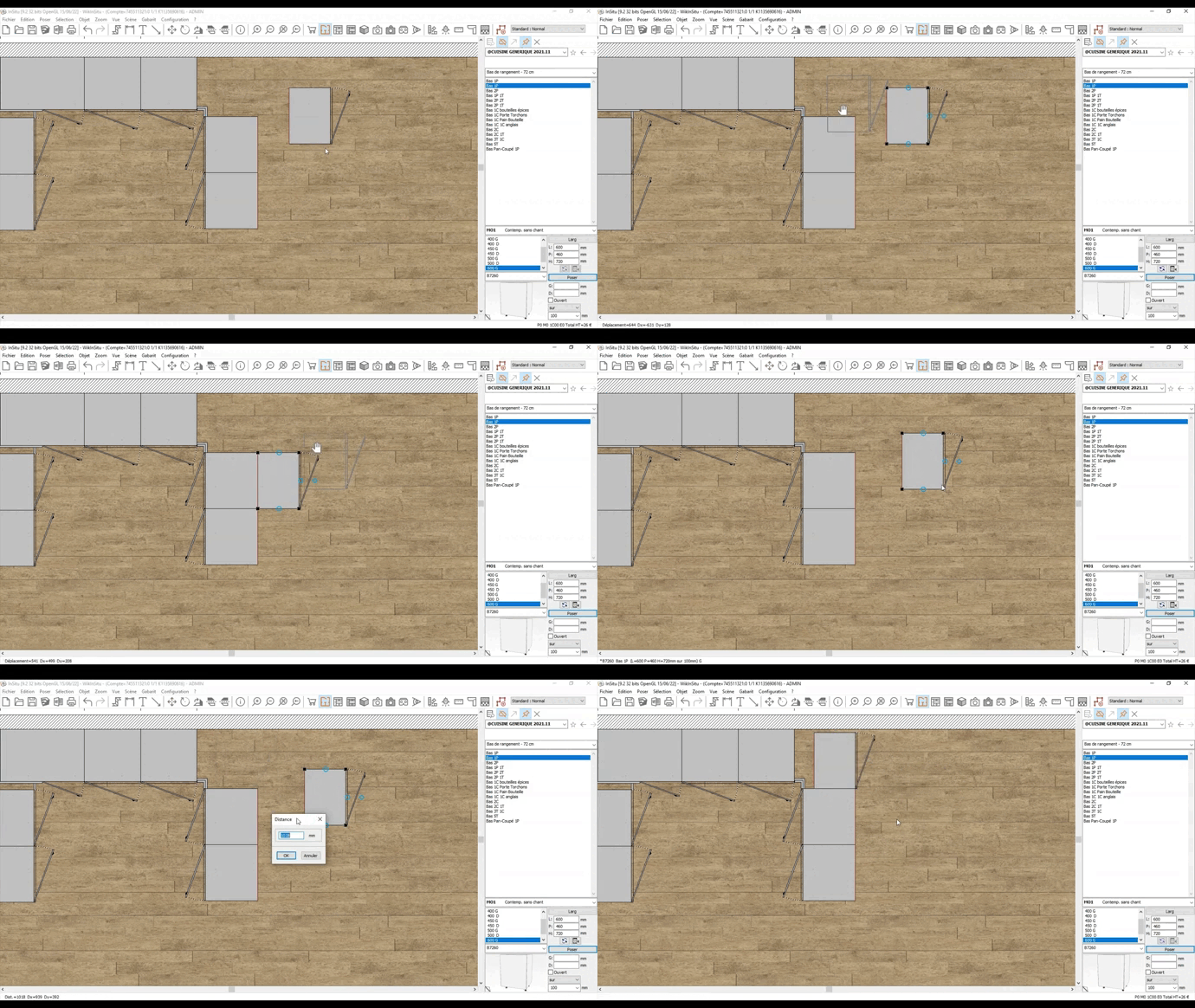
The move tool is a reliable tool used to move objects in a scene in a very precise fashion. Indeed, with the tool you can decide to move an object in a certain direction a precise distance. We have previously seen that InSitu relies on anchorage points in order to automatically place elements, but in some cases, you will need to use the move tool so that you can ignore the automatic and imposed positioning of the software or simply because the element was not programmed to be anchored (such as objects imported from the 3D warehouse)
- Placing a worktop on an island with a 20mm overhang
- Placing two pieces of furniture next to each other but in the opposite direction In this example, we can see that the InSitu software wants to place these pieces of furniture back to back. The only solution is to use the "move" tool.
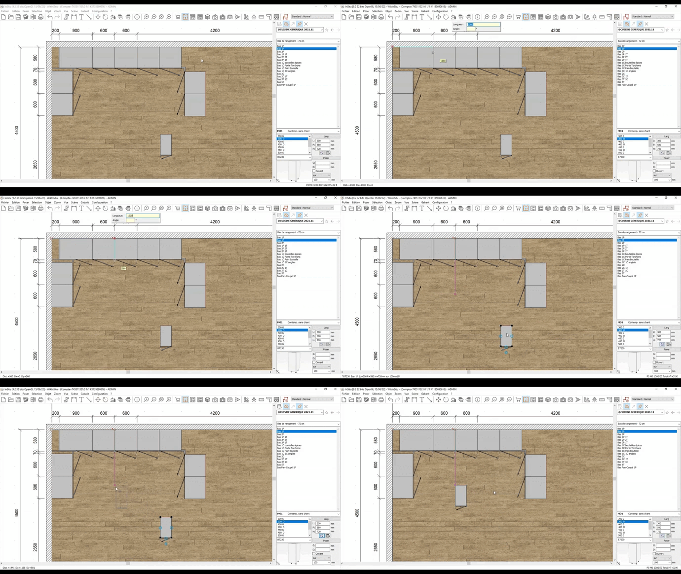
- Placing an island 1700 away from the left wall and 1500 from the high wall. Beforehand, we will use the "shape" tool to create an anchorage point. The move tool will allow us to position the piece of furniture on this anchorage point.
It is worth noting that the move tool deactivates the magnetisation. The moved object will be placed how you want it to without automatically repositioning itself. MEASURE TOOL
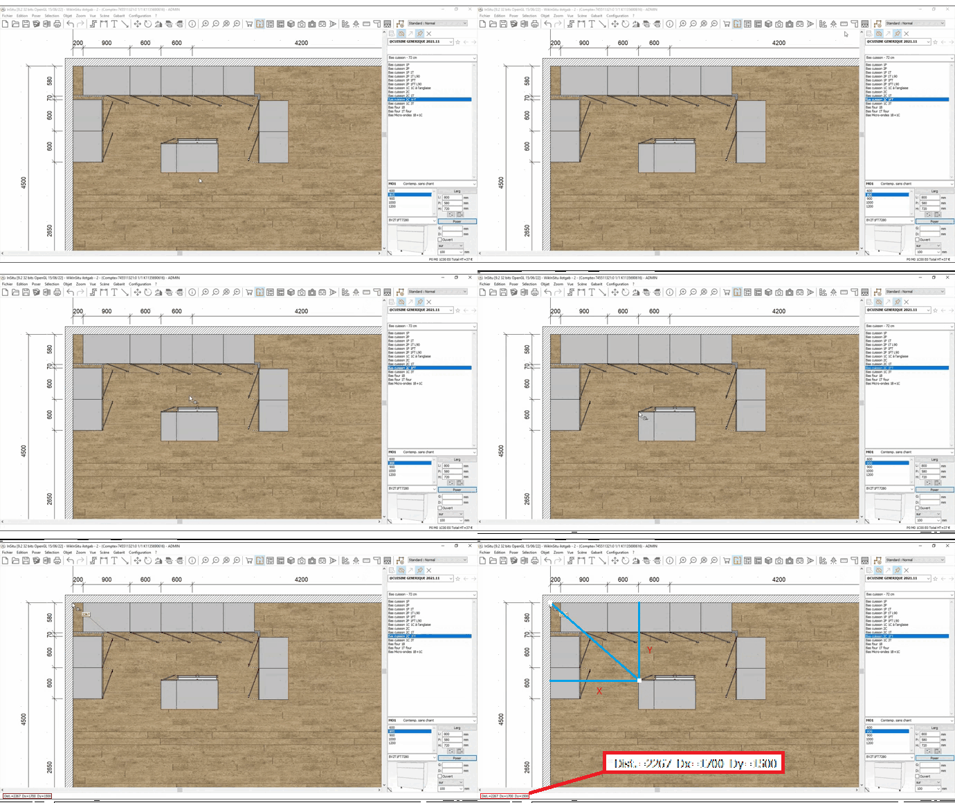
The measure tool is a tool that allows you to obtain precise and reliable measurements. Indeed, the tool makes use of the anchorage points of the various objects in a scene, therefore giving you precise measurements. In the following example, we need to know the measurements between the island and the left wall. By using the Measure button in your tool bar (also available via the scene drop down menu), you can measure the distance between 2 points. You will notice that when we try and measure from the island towards the wall, the measurements are imprecise... This is because, to obtain precise measurements, you will need to make use of anchorage points. These anchorage points are located on the angles of elements, meaning that there is no anchorage point in the middle of a wall, explaining the lack of precision. To perform the correct measurement, you need to proceed in the following manner: Measure from one corner of the island towards the corner of the wall. On the bottom left of your screen, three different measurements will appear: The first represents the distance between the two selected points the second X indicates the horizontal distance between the wall and the object the third Y corresponds to the vertical distance between the top of the wall and the object You therefore have measurements to the closest millimetre. You can also measure in an elevation view and the measurements are to be read in exactly the same way...
|
|
